Geometry
Ergonomic Recumbent Design
When I started my recumbent trike building project I was told in an online forum,
"ride as many recumbents as you can
and copy the ones you like".Well where I live there are almost no other recumbents, let alone trikes, so I had to start from scratch. If you find yourself in a similar predicament, then this data is for you. The following diagrams outline an ergonomic approach to designing recumbent bikes. I have found it to work in my designs. The measurements were originally taken from the NASA MSIS Anthropometric Tables (90 percentile of human beings), but have been refined with practical experience and advice from other builders. I have also borrowed some ideas from Bikesmith's 12 Steps to Designing a Great Handling Recumbent. This is definitely an area where I would like to do more research and see more practical information shared.
The process starts with the individual dimensions of the rider, seated comfortably in a reclined position, then the bottom bracket and handle bars are placed where they should be, from there informed choices are made about the appropriate wheelbase and head tube angle based on the desired seat height and backrest angle.
The following steps can be used, regardless of whether you are designing a LWB, a SWB or a trike. Items with range values should ideally be adjustable within those ranges, or alternatively matched to the individual rider. If you find any errors, please let me know. All measurements are in millimeters, unless otherwise noted.
The 12 Step Process
Step 1: Performing all the individual measurements described in the Basic Anthropometric Data section, and place the values in a table like the following for easy reference. If this is you first time reading this, you can skip this step for now and come back to it when you are ready to start your design.
Anthropometric Range Backrest-Angle 30° to 40° Backrest-Length 450mm BB-BOS (800mm to 1100mm) - CL BB-Clearance 350mm to 400mm BB-HB CL + 600mm + TC BB-Height 400mm (min) BB-Seat-Diff 150mm to 250mm CL (Crank Length) 145mm to 175mm HB-BOS 470mm to 610mm HB-TOS 490mm to 650mm Lumbar-Support-Height 190mm Saddle-Length 230mm Seat-Height 400mm to 470mm* Shoulder-Support-Length 120mm TC (Turning Clearance) 150mm to 200mm *this value is only a guide
Start by drawing the seat
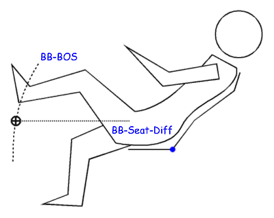
Step 2: Using your favorite CAD software, start by drawing the seat. If the BB-Seat-Diff is 150mm or less, the saddle (seat base) can be level with the ground plane, higher values and you might tilt the saddle up 5° at the front.
Place the bottom bracket in relation to the seat
Step 3: Draw an arc using the BB-BOS value as the radius centered on the back of the saddle. Now draw a horizontal line BB-Seat-Diff above the base of the seat. Place the bottom bracket at the intersection of this arc and line.
Mark the heal clearance
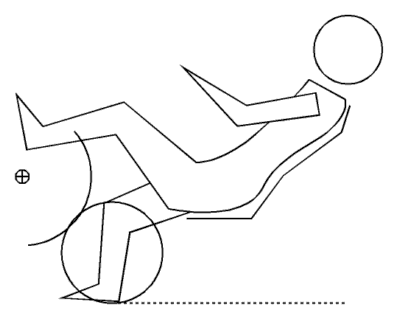
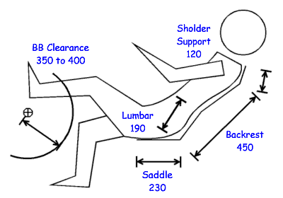
Step 4: Draw an arc centered on the Bottom-Bracket axis using the BB-Clearance value.
Place the front wheel (fixed BB)
Step 5a: For FWD twist chain drivetrain or regular RWD designs, draw a circle for the front wheel so that it is tangential to both BB-Clearance arc and the ground plane.
Place the wheel (moving BB)
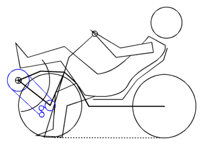
Step 5b: For FWD moving BB designs, draw a 100mm to 150mm arc around the front wheel axle for the rear derailleur clearance, then place the front wheel so that this arc is tangential to the BB-Clearance arc and the front wheel is tangential to the ground plane. Obviously the wheel must not overlap the bottom bracket, or the front of the seat, and it must provide plenty of clearance for the riders crutch.
Mark the trail intersection
Step 6: Mark a point forward of the front wheel contact patch using the estimated Trail value. At this point you should guess that the pivot angle (head tube angle) will be somewhere between 70° and 80° for FWD twist chain drivetrain or regular RWD designs and somewhere between 55° and 65° for FWD moving BB designs.
Position the handle bars
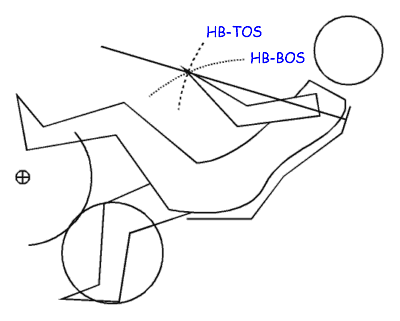
Step 7: Draw an arc using the HB-TOS value as the radius centered on the base of the Shoulder Support. Draw another arc with a 550mm (HB-BOS) radius centered on the back of the saddle. If you are planning to use a narrow handle bar with a tiller, the intersection of these arcs is where you should place your handle bars. Draw a line from this intersection to the center of the Shoulder Support. The Shoulder Support should be perpendicular to this line.
Adjust the handle bar position
Step 8: If you are planning to have a wide handle bar (recommended for FWD moving BB designs), draw an arc using the BB-HB clearance value centered on the bottom bracket axis. The intersection of this arc and the HB-TOS arc constructed in previous step is where the handle bar should be placed. This point should reside within the HB-BOS range, if its not, you may need to adjust the Backrest-Angle. Avoid the placing the handle bars closer than the HB-TOS, this will compromise tactility and make the steering awkward. Conversely placing the handle bars further than the HB-TOS will be less comfortable and make low speed control difficult, because larger adjustments may require you to let go with the outside hand.
Derive the steering tube axis
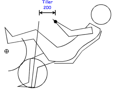
Step 9: For tillered handle bars, mark a point 200mm horizontally in front of the handle bars, then draw a line from this point, to the trail mark point on the ground plane. This line represents the head tube axis. Measure its angle, and revise the Trail value.
Position the rear wheel
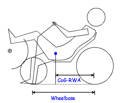
Step 10: Draw the rear wheel behind the seat, tangential to the ground plane. For regular RWD designs, ensure that at least 30% of the riders weight is on the front wheel. For FWD designs, about 60% of the riders weight should be on the front wheel. Calculate this by drawing a line from the CoG to the ground plane. The CoG will be about 150mm to 200mm in front of the back of the saddle, depending on the seat angle. Now divide the CoG to Rear Wheel Axle (CoG-RWA) by the wheelbase. Convert it to a percentage and you have your weight distribution ratio.
Adjust the rear wheel position
Step 11: The size of the rear wheel will influence the height of the seat, as will the wheelbase. If you want a lower seat height, you will have to increase the wheelbase, conversely if you want a shorter wheelbase, you will have to raise the seat. However you should also consider the tipping point. On the Why Does Tilting Matter? page, I described a method of calculating the tipping point. Basically, you draw a point half way between the front and rear wheel contact patches that is half the wheelbase above the ground plane. Then you form a triangle by drawing lines from the front and rear contact patches to this point. If the rider CoG is in front of this triangle, then the bike may tip forward when breaking. So you may want to adjust your seat height and wheelbase to place the rider CoG back inside this triangle.
Step 12: The final thing is to do is route the chain. This is a critical step, and you must do it as accurately as possible in your plans before you build anything. To start with, you need to take some chainring and cassette measurements. The following table has the sprocket measurements I use, depending on my drive wheel size:
Teeth Diameter 58t 240mm 53t 220mm 50t 205mm 39t 165mm 30t 125mm 28t 120mm 13t 60mm 11t 50mm Sometimes all you need to worry about is the biggest sprockets, but other times you need to consider everything, big-to-big, big-to-small, small-to-big and small-to-small.
FWD twist chain routing
The advantage of a twist chain design is that it does not suffer from pedal induced steering like the moving BB approach. The advantage of FWD designs, is that they can easily be designed to be separable. For instance, the front and back half can be joined with quick release coupler, and bike be taken apart and placed in the boot of a car without having to remove the drive wheel or chain.
Regular RWD chain routing
The advantage of RWD recumbent's and tadpole trikes is they have better grip climbing steep or slippery inclines (gravel roads). The disadvantage is that the chainline can be complex. All those extra chain guides and pulleys also decrease efficiency. However designs exist, like the Cycloratio, that have a straight chain path, but the rider CoG is forward of the Tipping Point.
FWD moving BB chain routing
Clearly FWD moving BB designs have the simplest chain path, provided the stays are placed appropriately, however these designs require some riding time to master.
Basic Anthropometric Data
- BB-BOS
- Bottom Bracket to Back of Seat
I prefer to measure to the back of the saddle rather than the front, because the saddle length of seats can differ significantly enough to warrant it. This value should be 800mm to 1100mm minus the Crank Length (CL). The following table shows the range of values for various crank lengths.
CL Min Median Max 150mm 650mm 800mm 950mm 160mm 640mm 790mm 940mm 170mm 630mm 780mm 930mm
- You can calculate the correct value by sitting up against a wall and having someone measure from the wall to the base of your foot, then subtract the Crank Length, finally subtract an additional 100mm, and you will have your persoal BB-BOS measurement. Nevertheless, you should try to make your bottom bracket adjustable, with either a telescopic boom, or sleeve mount.
- BB-Height
- Bottom Bracket Height
The recommended BB-Height is a function of the Seat-Height and the BB-Seat-Diff. The minimum value should be 400mm, however with FWD moving BB designs (TT/Speculoos) I would recommend 500mm -- because the bottom bracket tends to lean into the corner.- BB-Seat-Diff
- Bottom Bracket Seat Difference
A value of 150mm above the seat seems to be what most recumbent cyclists prefer, however for FWD moving BB designs, the BB-Seat-Diff should be closer to 50mm. Obviously the further back the seat angle the higher the BB-Seat-Diff value should be, 150mm for 40°, 250mm for 30°, and 300mm for 20°. If the BB-Seat-Diff value is too low, the buttock muscles become obtuse and rob the rider of full power, while too high a value may feel awkward and potentially cause the knees to obscure the rider line-of-sight, while only providing modest gains in aerodynamic efficiency.- Seat-Height
- This is the recommended hight for chairs. It places your feet comfortable square to the ground, so it provides a useful benchmark against which to compare potential designs.
- BB-HB
- Bottom Bracket to Handle Bar Clearance
This clearance value is necessary if you are planning to have a handle bar that is wide enough to interfere with your knees. It is the minimum distance from the bottom bracket to the handle bar, and assumes that your knuckles are level with your knees. If the handle bar is closer to your stomach, you may need a larger BB-HB value to prevent interference from your thighs. To compute this value, add 600mm to the Crank Length, then add the Turning Clearance (TC) of the handle bar. For a moving BB design, this value doesn't need to be much more than about 100mm, because your legs turn with the handle bars. For fixed BB designs, you need to add the forward travel distance of the handle bar at approximately 45°.- HB-TOS
- Handle Bar to Top of Sholder support
To calculate this value, stand against a wall and have someone measure the distance form the wall to your wrist, then subtract 50mm, and you will have your persoal HB-TOS measurement.- HB-BOS
- Handle Bar to Back of Seat
This value establishes the height the handle bar should be above the seat. There is quite a range here, with larger values reflecting higher backrest angles, the important thing is that your knuckles line up with your knees. To calculate this value, stand up against a wall, lift your knee and have someone measure from the wall to the center of your knee pivot.
- BB-Clearance
- Bottom Bracket Clearance
This is the distance from the bottom bracket to anything behind it that you may hit with the heal of your shoe. This includes derailleurs in moving BB designs, and the front wheel in fixed BB designs. For things you might hit in front of the bottom bracket, draw an arc that is 50mm to 100mm longer than the Crank Length.- Saddle-Length
- This is the length of the saddle or base of the seat from the front edge to the base of the backrest.
- Backrest-Length
- This is the length of the backrest from the rear of the saddle to the base of the sholder and neck rest support.
- Sholder-Support-Length
- This is the length from the top of the backrest to the top of the seat. It helps to keep the rider from slipping up the seat when exerting high pedal forces. For solid, single piece seats (like carbon fiber) the shoulder support may be integrated with the neckrest. For mesh seats, its is better to keep the shoulder support short and have a separate neckrest, because a high wide seat back contributes unnecessary aerodynamic drag.
- Lumbar-Support-Height
- Including lumbar support in your seat can improve long term rider comfort, as well as preventing the rider from slipping backward and up the seat when exerting high pedal forces. A good angle of the lumber support is about 190°.
- Backrest-Angle
- This value comes down to personal taste. The larger the angle, the easier it is to balance, and the more comfortable it is on your neck, but the recumbent will be less aerodynamic. Much above 40° and you start to put more weight on your posterior, and the resulting 'recumbent butt' makes touring less comfortable. Much below 30° and the bike requires greater skill to balance and the rider line-of-sight can also be impaired.
Copyright © 2007 Henry Thomas
![]()

