Drive Train Construction
Before you start debur and wire brush all the metal pieces.
The drive train is actually quite challenging. The most important thing to keep in mind is the boom must remain square to the steering pivot and the front axle.
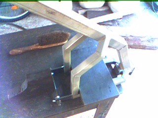
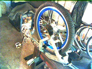
This is what the almost finished drive train looks like. I decided to wait until the rest of the bike was done, before adding the tiller, just to make sure that the steering position was to my liking.
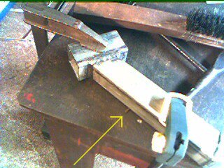
I started by clamping the pieces of the boom (Items 14 & 15) to the work bench. Next I tacked all four corners then welding them together.
Next I placed some spent 2.5 mm welding rods under the boom (above arrow) in two places to raise it off the bench and center it against the Big C bracket (Item 10). Like before these were all clamped, tacked then welded.
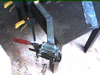
Now I bolted the pivot spindle with a washer on each side to the Big C hinge plates (Items 34). This was clamped and tacked and then welded.
For each of the forks (Items 26 & 27) I clamped them square and welded them.
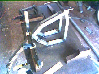
To clamp the diagonals (Items 24 & 28), I clamped thme to a large piece of channel I have that is cut at 45° on each end. This certainly makes clamping and welding bits like this easier. Its amazing how handy off cuts from a scrap metal yard can be.
To weld the forks to the boom, I started by clamping the boom square to my work bench. Then I placed one fork one each side and put that large 1" bit of plate on them to hold them in place while I tack welded them. One was a bit out so I ground off some the offending tacks, bent it true and re-tacked. Finally when I was happy with it I welded the forks to the boom starting on the front and back edges, alternating from side to side, and then finally the side edges. This was to prevent the heat effected zone and weld bead pulling the forks our of true.
Here I have one piece of 1" plate resting on the forks and the other holding the dropouts in place. The dropouts are bolted together with and old Axle spaced at 125mm. This holds them nice and square. Start by tacking the front and back 6mm faces, but don't weld them yet!
Next I assembled the front wheel and attached the cranks on the BB Mount. I checked that everything was true -- which it was -- the wheel was dead center and the big chainring lined up with 4th on the cassette and the small chainring lined up with 3rd on the cassette. All that looked good so I removed the front wheel and crankes, bolted the old Axle back on and welded the dropouts onto the forks, ready to complete the final welds. Weld half a length at a time, alternating sides, starting with the outside first.
The final job is to weld the endcap onto the end of the boom. When you have done that you need to grind the weld beads back flush with the faces so the BB Mount will still slip on.
The handle bar binder is constructed in much the same way as BB Mount binder, only the wider aperture is only 12.5mm to the center. Here I am clamping the binder to the end of the tiller, ready to weld. In the end, I decided to put the binder on the bottom, rather than the top -- as in the plans.
Once welded, cut the binder down the center using a hacksaw.
Then using the rotary tool, widen the inside face to maximize the travel.
Here I have clamped and tack welded Item 30 to the center of the top pivot hinge. Only tack this is one corner at this stage, make the tack substantial enough to bend without snapping off, but not too large.
Now using a length of RHS clamped to the boom (with spacers to avoid the top weld bead), use two lengths of plate to position the tiller on the drive train as shown above. This will help you get the alignment right. Again, only tack these together in one place. Now un-clamp everything and check the alignment. User a hammer to tap the tiller gently to correct it, if it is out. Once you are happy with the alignment tack each join once more on the opposite side and check the alignment again. Once you are done weld the front and back welds of the support first, then do all the sides.
Here you can see the finished tiller with the handle bars mounted. You will notice that I chopped a bit off the front of the tiller to leave a gap. I did this for two reasons, 1). to let any moisture out that may come in the top, and 2). so I could run the break and front derailleur cables down inside the tiller stem.
I decided I needed some wider handle bars, so I got this set from the local bike shop. To mount them I decided to dispense with the telescopic binder and simply welded a binder I cut from a head set directly to the drive train stem.
Well it turns out I got the Trail measurement wrong in my steering geometry. I figured that the simplest way to fix this was to cut out the steering pivot hing, grind the mount surfaces so as to adjust the angle by 10°, then weld it back in place. This has the effect of increasing the Fork Offset and reducing the trail to 40mm, which is about where I now believe it should be.
Here you can see the drive train with the hinge cut out and I have begun grinding the top and rear edge of the boom with the cut off wheel on the angle grinder.
Here I am clamping the hinge back into place. As you can see I have used a long ½" bolt to help with the alignment. In this photo you can see that it is perfectly centered.
Here is the same view from the side. The ½" bolt is clamped at the top centered between the two forks and then the base was adjusted and clamped into place. First I tack welded in a few places, then welded the front and back before welding the sides.
Copyright © 2007 Henry Thomas
![]()


